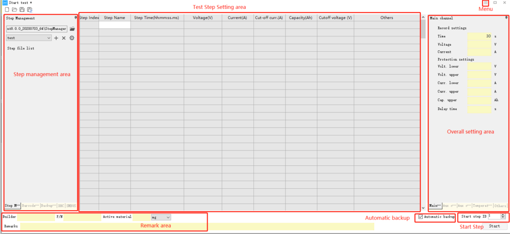
Neware BTS Software Client User Manual

Customized Expression with BTS Client

Expression

The difference between Test Step Setting and Expression:

Test Step Setting is for saving test build parameters and the invocation of following Test Step Settings and Expressions.

Expression is an user-made inequation as the cut-off condition of a Test Step. When the setting of the inequation is satisfied, the test will go to the assigned Test Step.

Remark: Expression only works in BTS8.0(middle machine version).
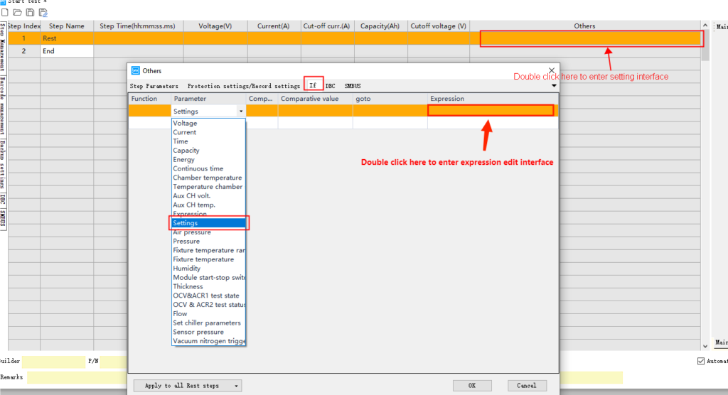
1 Setting

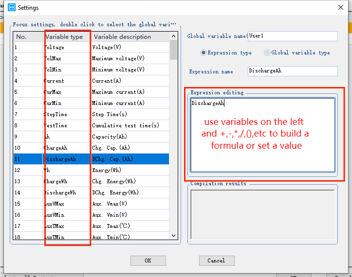
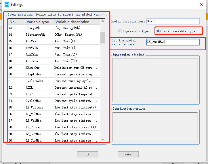
There are two types of setting, expression type and global variable type.

The name of Global variable means exactly the same as its function.

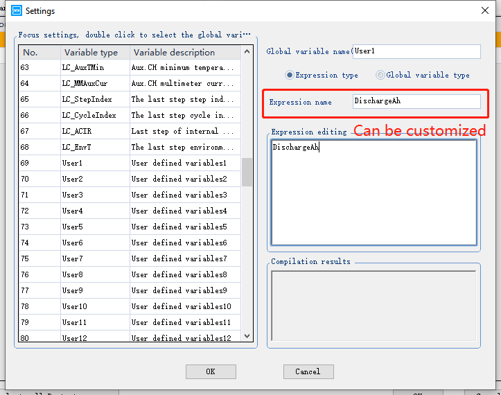
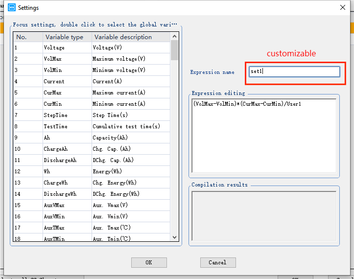
The Expression name which can be customized does not have an actual meaning.

Expression Setting Steps:

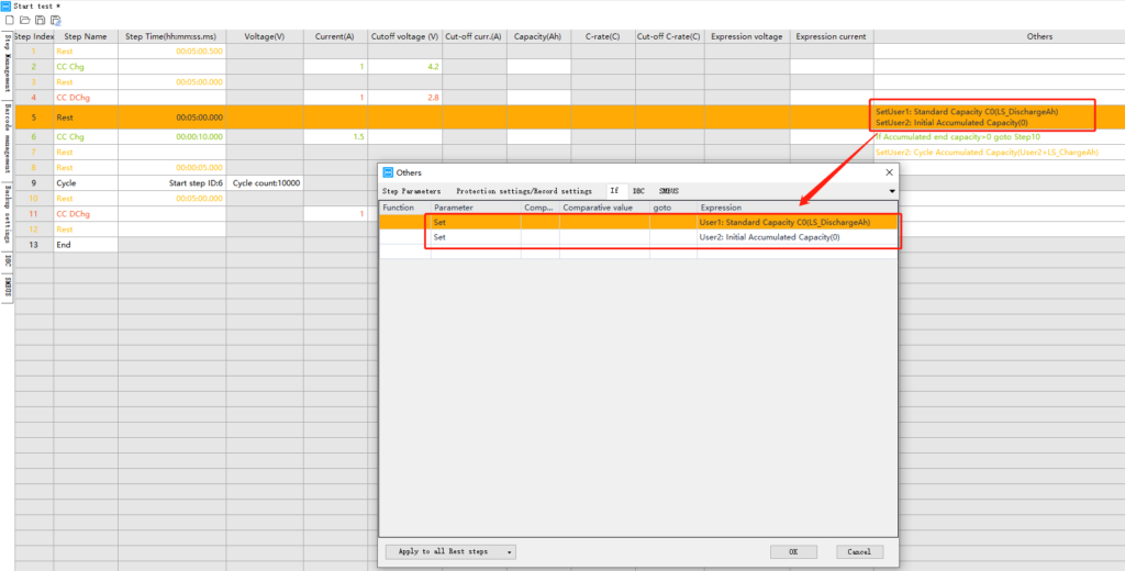
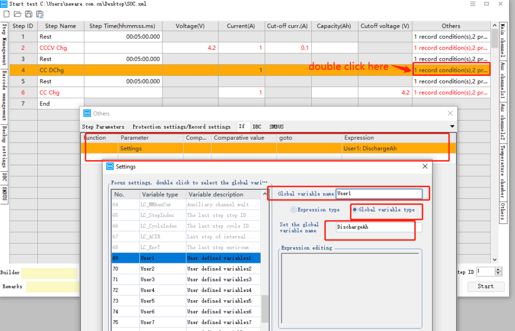
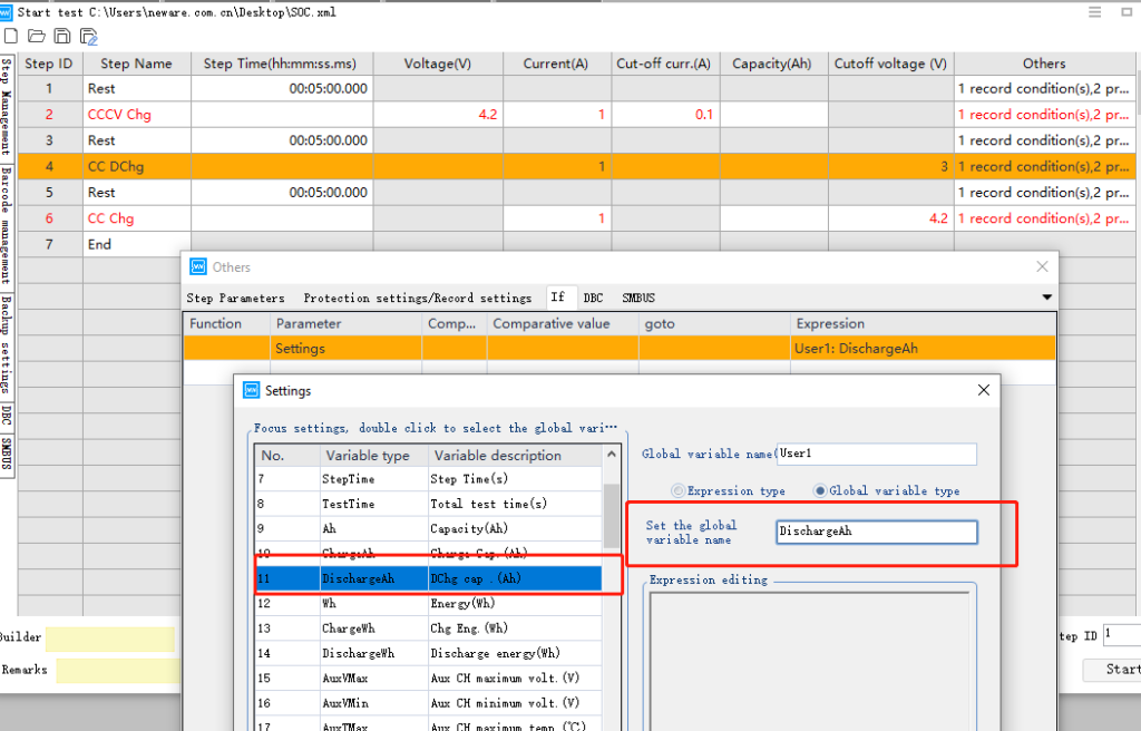
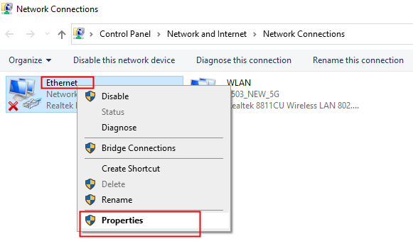
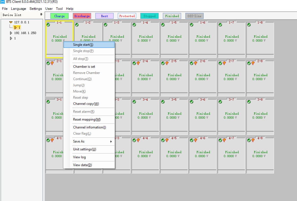
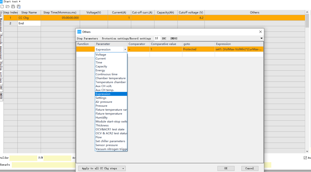
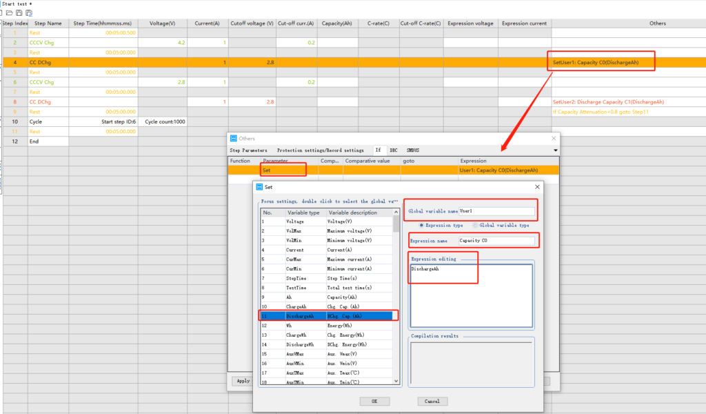
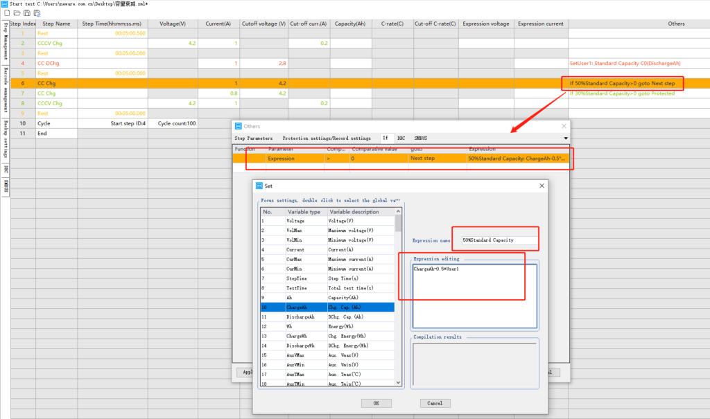
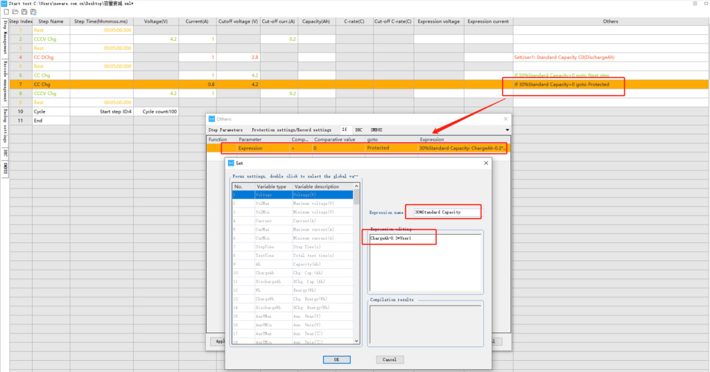
  1. Click ‘other’section for a certain test step → go to ‘if’ → select ‘settings’

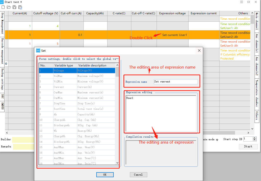
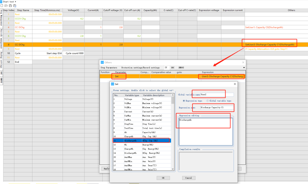
  1. To customize the global variable name, selecting from User1~User50. Double click the parameter to input to avoid the manual input error.

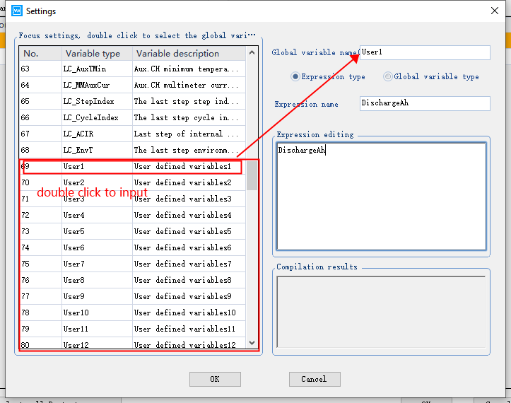
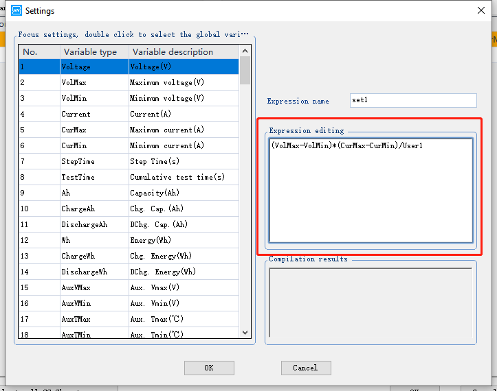
  1. Expression name can be customized

  1. Expression editing

Notice:

  1. Notice the unit of each variable

  2. “75*Ah”can not be inputted as “0.75Ah”

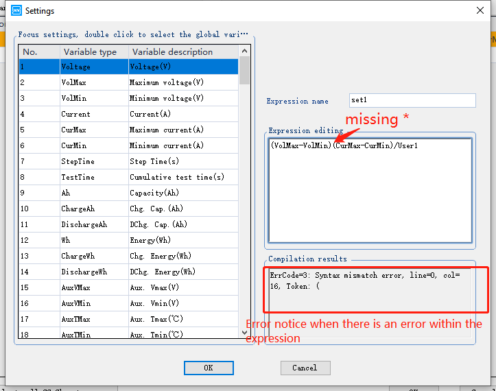
  3. For example, “3*Ah*(VolMax-VolMin)*(CurMax+CurMin)/User2” can not be inputted as “3Ah(VolMax-VolMin)(CurMax+CurMin)/User1” and “*” can not be missed while inputting.

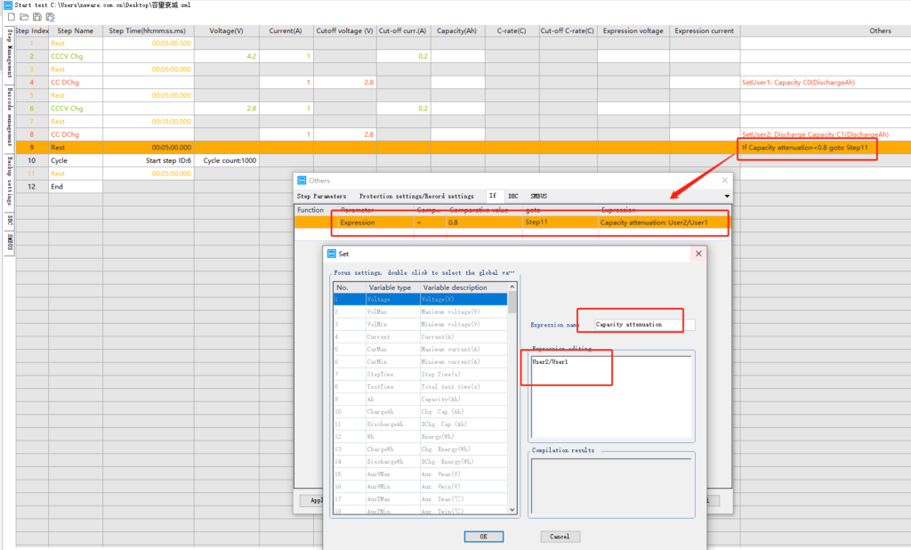
  4. When a expression has a customized variable like point 3 indicated, the “User2”has to be set a formula or a value

  1. When select global variable type, the global variable name to be set can only be selected from the global variable.

2. Add Expression

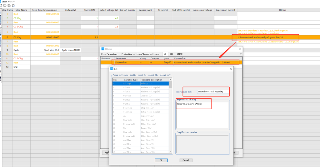
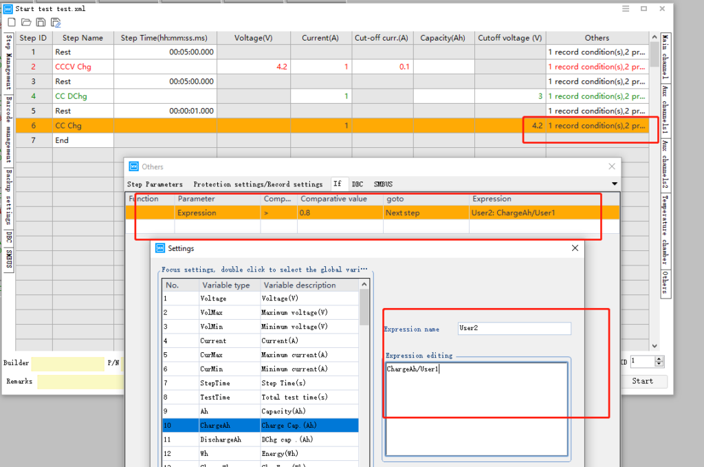
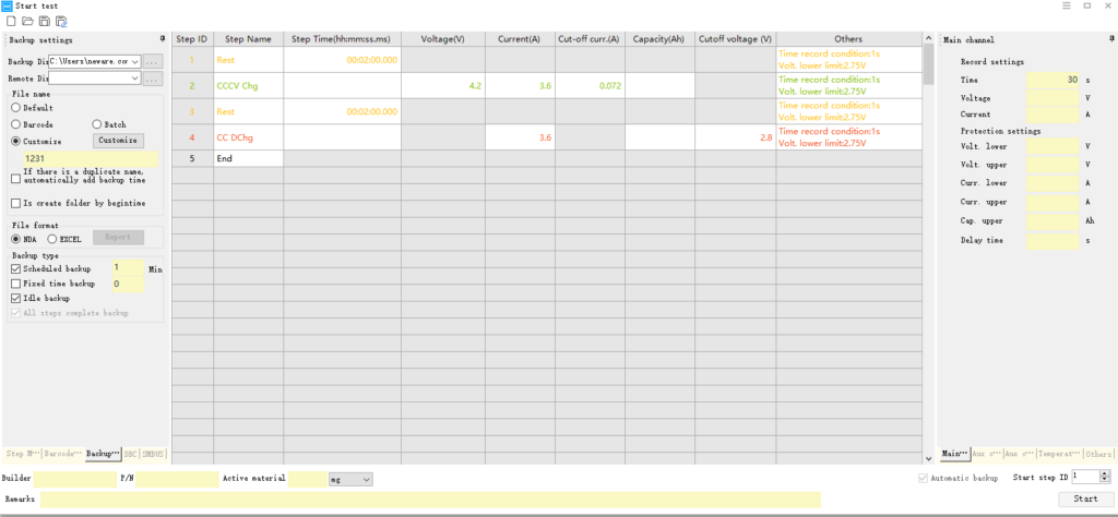
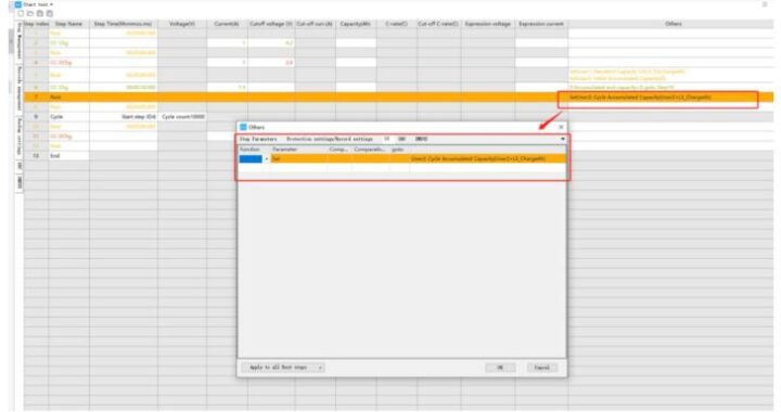
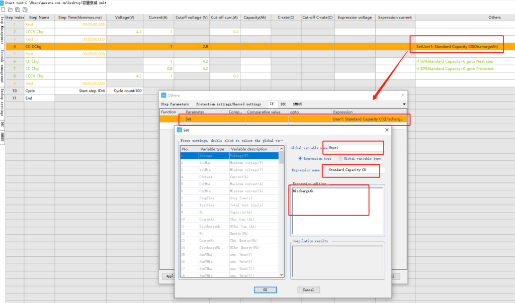
Add expression function is for user to edit the expression as the cut-off condition of certain test step.

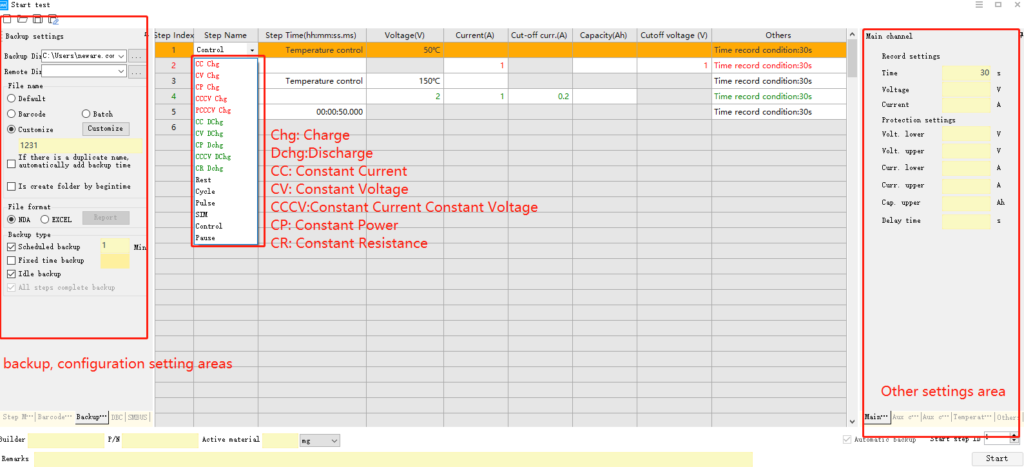
  1. As picture below shows, it adds a expression for cc charge step, the comparator, comparative value and goto can be set based on the application.

  1. The express name is named by the user.

  1. Expression editing is customized expression.

Notice: “*” can not be missed, for example, “3*Ah*(VolMax-VolMin)*(CurMax+CurMin)/User2” is correct and “3Ah(VolMax-VolMin)(CurMax+CurMin)/User1” is wrong.

  1. Expression meaning reference:

Voltage:Current voltage of the channel

VolMax:Highest voltage of the channel under current test step

VolMin:Lowest voltage of the channel under current test step

StepTime: Running Time of current test step

Test Time: Time started from the start of the test

Ah:the accumulated capacity value start from the start of the test

Wh:the accumulated energy value start from the start of the test


3.Expression Current and Expression Voltage

The steps supported by the expression current: constant current charge, constant current discharge, constant current constant voltage charge, constant current constant voltage discharge.

The steps supported by the expression voltage: constant voltage charge, constant voltage discharge, constant current constant voltage charge, constant current constant voltage discharge

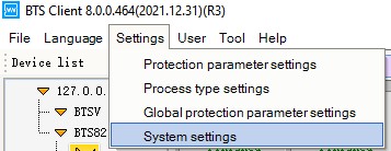
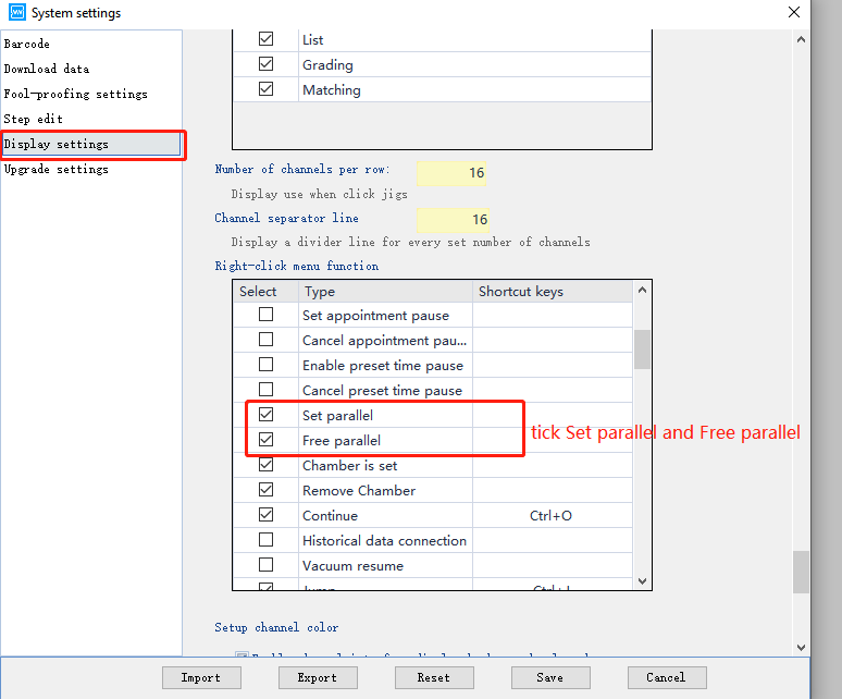
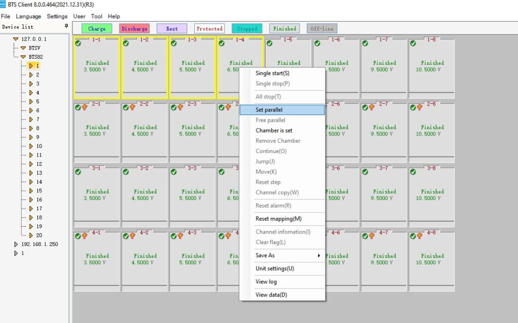
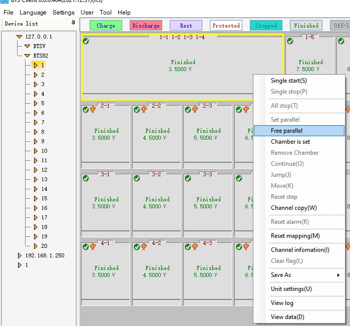
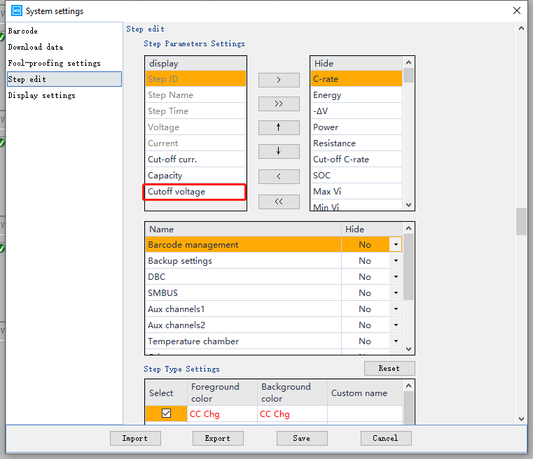
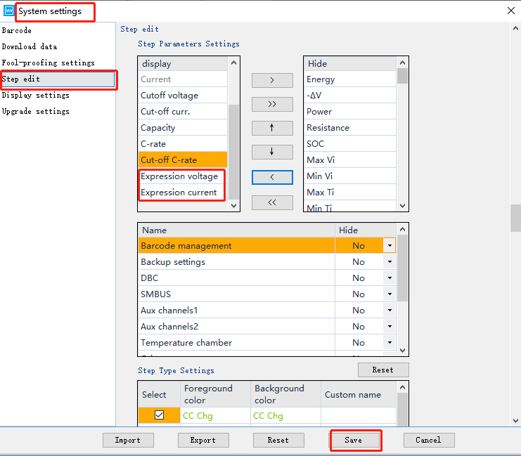
The expression current and expression voltage can be changed from hidden to displayed via <System settings>.

See the expression description for editing details on expression current and expression voltage

1. Expression current

Meaning: You can set the expression to limit the current value of the running step.


2. Expression voltage

Meaning:  You can set the expression to limit the voltage value of the running step.

4.The meaning of variable of Expression

  1. Voltage: Voltage(V)

  2. VolMax: Maximum voltage(V)

  3. VolMin: Minimum voltage(V)

  4. Current: Current(A)

  5. CurMax: Maximum current (A)

  6. CurMin: Minimum current (A)

  7. StepTime: Step Time(s)

  8. TestTime: Total test time(s)

  9. Ah: Capacity(Ah)

  10. ChargeAh: Chg. Cap(Ah)

  11. DischargeAh: DChg. Cap(Ah)

  12. Wh: Energy(Wh)

  13. ChargeWh: Chg.Energy(Wh)

  14. DischargeWh:  DChg.Energy(Wh)

  15. AuxVMax: Aux.Vmax(V)

  16. AuxVMin: Aux.Vmin(V)

  17. AuxTMax: Aux.Tmax(℃)

  18. AuxTMin:Tmin(℃)

  19. MMAuxCur: Multimeter aux CH curr.(A)

  20. StepIndex: Current operation step index

  21. CycleIndex: Current Running cycle index

  22. ACIR: Current internal AC resistance(Ω)

  23. EnvT:Current cycle temperature(℃)

  24. CycleVMax: Current cycle maximum voltage(V)

5.Samples

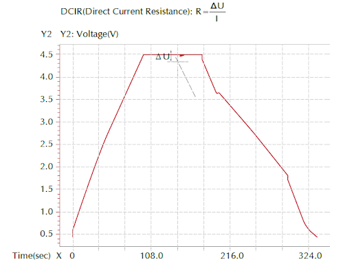
1. Capacity Attenuation


2. SOC


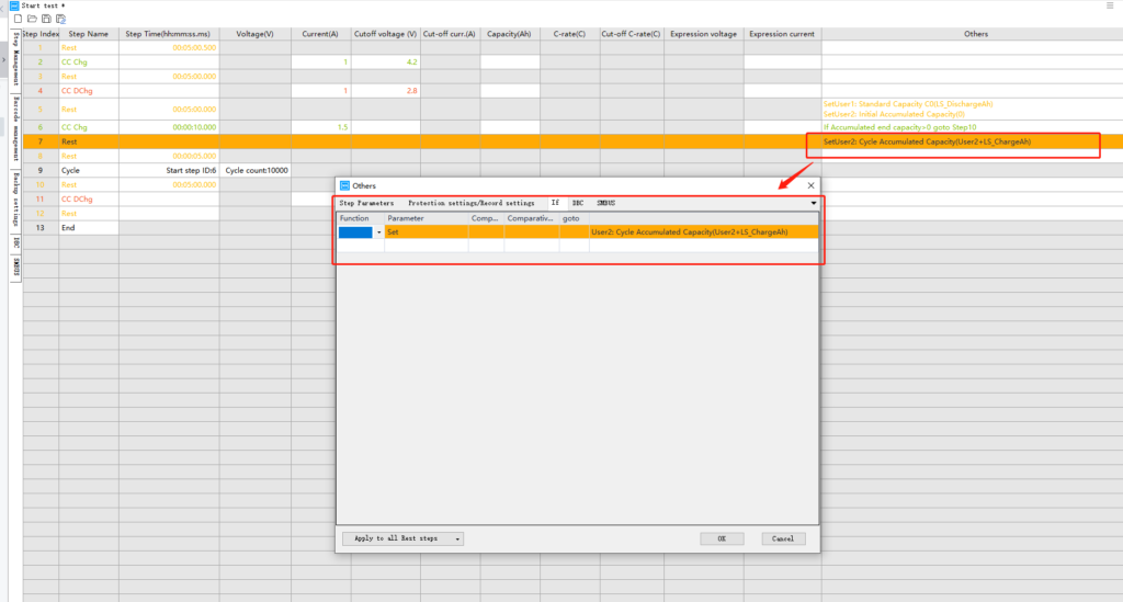
3.Accumulated capacity


cylindrical test equipment

How to set channel parallel and free parallel on Neware Battery Cyclers

This Article will show how to set channel Parallel and free channel Parallel on Neware Battery Testing System.

1.Settings → System settings

2.Display settings → Tick Set parallel and Free parallel →Click save

-  

3.Select channels that are needed to be paralleled, right click for turn on the menu, click Set parallel.

4.Parallel done

After the parallel is done, please connect all clamps from the paralleled channels to the corresponding polarity of the battery. For example, if two channels are paralleled, connect V+ and I+ test wire from two channels to the positive of the battery  and connect V- and I- from two channels to the negative of the battery.


Below will show how to Free Parallel

1.. Right click the paralleled channel, click Free parallel.

2.The paralleled channel is freed to single channels.

After free parallel, please also remember to free the test wires.

SOC Neware

How to set up SOC test with Neware Testers

SOC step build:

  1. Rest 5 min
  2. CCCV Charge 1000mA to 4.2V, cut-off current 100mA
  3. Rest 5 min
  4. CC Discharge to 3V and record the current dischargeAh
  5. Rest 5 min
  6. CC Charge 100mA to 80% of dischargeAh
  7. End


Notice:

The cutoff voltage need to be added into display.


Below is the instruction about how to customize and set the variables for recording the dischargeAh:


Below is how to use expression to end the test once the cell is charged to 80% of discharge:


Based on the above settings, ChargeAh/User1 means Charge capacity/ discharge capacity(recorded before)


Customer can adjust the variables and settings based on your need.


How to set up GITT test with Neware Battery Tester

This Article will show how to set up a GITT test with Neware Battery Tester

1.Firstly set the test step as the picture below, using rest – CC discharge with 0.1C  – rest – cc charge with 0.1C

2. Go to Data View interface, click the parameter settings in right click menu.


3.Untick single step and tick enable capacity accumulation


4.Right click the bar above the curve graph area and click curve settings


5.Set Capacity on X axis and Voltage on Y1 axis

6.After all settings, the display of time and capacity are accumulated. The data shown below is generated from virtual machine, just for reference only.


DCIR checking for Neware Battery Tester

How to get DCIR by using Neware Machines

This article will Show how to get DCIR by using Neware Machines


1.Open the BTSDA interface, open the data in BTSDA, right click the data record area and click DCIR.


2.Click Step DCIR or Pulse DCIR depending on real situation.


3.Select “Calculate DCIR using adjacent steps that meet the following combination”, please make sure the two steps set are indeed adjacent, then click “add”. Select Last record on section V1 & I1, select First Record on section V2 & I2.


4.After the record below come out, click OK.

5.DCIR data will display here


Direct Current Internal resistance(DCIR) is one of the important indexes to evaluate battery performance. The test of internal resistance includes AC internal resistance and DC internal resistance. For single-body cells, ac internal resistance is generally used to evaluate, which is often called ohmic internal resistance. However, for large battery pack applications, such as electric vehicle power systems, due to the limitations of test equipment and other aspects, it is impossible or inconvenient to directly test the AC internal resistance. Generally, dc internal resistance is used to evaluate the battery pack characteristics. In practical applications, dc internal resistance is also used to evaluate battery health, make life predictions, and estimate system SOC, output/input capacity, etc. In production, it can be used to detect faulty batteries such as micro-short circuits.

The test principle of DC internal resistance is to apply a large current (charge or discharge) to the battery or battery pack for a short time. Under the condition that the battery has not reached complete polarization, the dc internal resistance of the battery is calculated according to the voltage change of the battery before and after applying the current and the applied current. Four parameters must be selected to test dc resistance: current (or adopted multiplier), pulse time, SOC, and ambient temperature. These parameters have a great influence on dc internal resistance.

The formula for DCIR is: R= UT-U0 / I

R: dc resistance, Ω

Ut: Voltage at time t of charging or discharging, V

U0: The battery voltage, V, before charging or discharging

I: Current, positive charge, negative discharge, A

Neware battery testers are able to test battery DCIR, all data will be displayed on neware self-developed software.

How to build a capacity test and cycle life test for Lithium batteries-Neware

How to build a capacity test and cycle life test for Lithium batteries

This article will show the test build of the Typical Lithium battery Capacity and Cycle Life Test.

Go to BTS client to build a test step:

Here is a sample test build, taking a typical 3.7V 3600mA lithium battery(18650) as an example.


  1. Rest for 2 mins
  2. CCCV Chg(Constant current Constant Voltage charge) the battery until it reaches its rated voltage and set a cut-off current at 0.02 or 0.05C.
  3. Rest for 2 mins
  4. CC DChg(Constant Current discharge) the battery until it reaches its cut-off voltage.


5. Here is a sample test build for cycle capacity/cycle life test:


5. After the test is done, the test result can be viewed in BTSDA.


Neware products collection

User Guidance- How to set up Neware Testers

This article will introduce a quick guide on how to start to use Neware BTS when you receive Neware's battery tester just now. There are several steps in the following part. Just follow it. Let's begin now.


Step 1. Set up hardware


1.Firstly, connect the testers with PC:

To use the ethernet cable to connect mid machines by TCP/IP port from PC or a router(if applicant), then connect the mid machine to the testers by connecting RS485 ports(Figure 1). If there is more than 1 tester need to be connected, connect them by connecting the RS485 ports(Figure 2). For those whose mid machine is embedded in the machine, the ethernet cable should be connect directly to the machines’ TCP/IP port(Figure 3) .


Figure 1. Sketch map of hardware and software connection way for 1 and multiple devices


Figure 2. Connect multiple testers

Figure 3. Embedded middle machines’ TCP/IP port


2. Connect the batteries with clamps and universal holder in order(Figure 4). Ensure that everything is connected tightly and correctly

Figure 4. Battery, clamps and universal holder connection.


3. Turn on the computer, middle machines and testers(Figure 5).

Figure 5. Turn on machines


Step 2. Middle machine settings

1. After turn on the middle machine, the screen will show information as below. Select “Configuration”then press “√”.

2. Change the “Get IP Addr”to “Manual”

3. Set the LP, GW and SP in the same network segment(the first three code should be the same), the GW’s last code has to be 1. The last code of LP should be the same as Device ID(here is 3).


4. If changes need to be changed, press ”√” to enter the setting interface and use “√” to select the column that needs to be changed and press ”↑” or ”↓” to amend the value. After the change is done, press ”√” until the interface goes back to previous menu.


Step 3. Computer settings

1. Enter the Network and sharing center and click Change adapter settings

2. Right click “Ethernet” and click Properties for setting


3. Double click TCP/IPv4


4. Set the IP address the same value as SP(7th parameter on the middle machine), set the Subnet mask the same value as GW(6th parameter on middle machine).


Step 4: BTS software installation

1.Download link is: BTS 8.0 Download link

2.There are four sections to download:


Step 5. Set up the BTS Client

1. Click “User” and click  ”User Log in”


2. Default User name:admin, default Password: neware

3. Find the middle machine that needs to be set up and select/click the middle machine ID


4. Channel mapping phase, right click the gray area on the right side of the device list and click “reset mapping”


5.Right click the table area on the right side then click “Main CH default mapping”, then click “1x8”. If there is Aux channel mapping requirement, please do the same by clicking “Aux CH default mapping” and “1x8”.


6. Click “save mapping”


7. Mapping done


Step 6. Start test

1. Right click a single channel or select multiple channels and click “single start ” to create a test build.


2. Select multiple channels to bulk start


3. Edit settings and click “Start” in the right bottom corner to start the test


4. Right click the channel for more test action.


Step 7. Data View

1. Right click the channel and click “View Data”


2. Enter BTSDA(BTS data analysis software) interface


Step 8. Data Export

1. Right click any area and click “Export”


2. Select Layer report and set the save path and file name.


3. Exported Excel file


4. Save data content as NDAX file by “Save As” for BTSDA to load


For more support, please feel free to contact:support@newarebatterytester.cn